
Pose Estimation from Aruco Fiducials in OpenCV
I have been working through the SLAM book and also working on building a robot from scratch with some cheap parts as I go. My goal is to learn all the theory behind Monocular Visual SLAM and implement it on my robot.
I started off doing localization from fiducials, which was a concept I got exposed to during my brief stint at Amazon Robotics. The core idea is this: you have some marker, with an ID, that you place in the world. You use some fancy algorithm to detect the marker. Then you can figure out its ID and the pixel coordinates of its four corners. You use the ID to grab the known coordinates of the four corners in 3D. If the camera parameters are known (the pinhole camera matrix, K), then you can figure out the position and rotation of the camera.
In this blog post I want to walk you through that whole process. I will gloss over some of the theory but provide links to the resources you can use if you want to understand the fundamentals. Let’s get started with some of the fundamental concepts.
Requirements
- OpenCV installation and OpenCV with Python
- Access to a Printer
- Basic knowledge of Linear Algebra
- Know what the word “optimization” means
The Camera Matrix
The first step is going to be “calibrating the camera”. Hopefully this image should clarify the problem a bit:
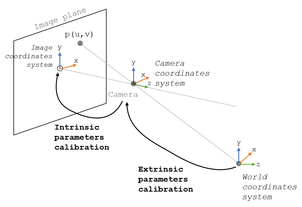
The intrinsic parameters are what we aim to find in this step. The extrinsic matrix describes the rotation and translation that converts a 3D point from world coordinates to camera coordinates. The intrinsic matrix describes a transformation from 3D camera coordinates, into 2D coordinates of the image.
Helpful Tip: If you aren’t familiar with Homogeneous Transform Matrices I recommend checking out chapter 3 of Modern Robotics
The way to do this is to take a lot of pictures of a 3D object with lots of different known points. Given the orientation of those points relative to each other, we can figure out the position of the 3D object relative to our camera. From there it becomes an optimization problem to figure out the intrinsic camera parameters that map the 3D points to 2D. Using a checkerboard pattern is the easiest way to have the relative spacing and orientation of the 3D points be known.
If that sounds like a lot of unpleasant math, fear not! OpenCV provides an out of the box solution to calibrating the camera. You can follow the steps below fairly mindlessly and get this piece of puzzle done.
No-Fear Camera Calibration
- Download a calibration image, I use this one
- Print off your calibration image. The scale of the squares is important, you can measure the size of the squares with a pair of calipers or something. You’ll want to know their size very precisely in mm.
- Copy the following code from GeeksForGeeks
- Update this line of code:
objp[0,:,:2] = np.mgrid[0:CHECKERBOARD[0], 0:CHECKERBOARD[1]].T.reshape(-1, 2) * SQUARE_WIDTHWhere SQUARE_WIDTH is the measured value from step 2. This gives your camera matrix a sense of scale. Be aware that all of our measurements are going to be in mm in this tutorial.
- Take at least 14 pictures of the checkerboard with the camera you want to calibrate. I usually do about 25.
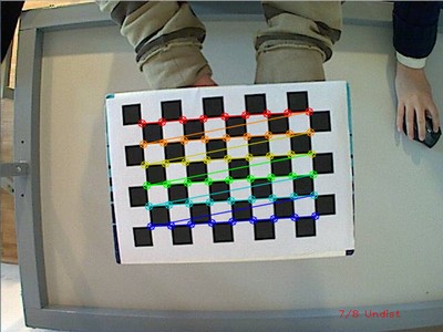
- Run the script on your images. Images with the corners of the checkerboard hilighted will pop up. You want the corner detections to be accurate. You should delete any images that don’t have corners detected, or have them detected improperly.
- Congratulations! If all things work properly you should see the Camera Matrix and Distortion coefficients. You can save these off to a json and load them later.
Helpful Tip: Take your calibration images at the same aspect ratio and resolution as the images you will take for localization. I ended up burning myself because I was capturing my calibration images for Raspberry Pi camera without using the video port, but was using the video port to stream my images during deployment.
Placing the Fiducials
This is the fun part (depending on your definition of fun). The first step is to print out your fiducial markers. That can be done here. I usually go with the Original Aruco dictionary, and print the first 10-20 markers. I have settled on 80mm as the width of the markers. When you cut these out, make sure you leave a decent amount of white space on the edges. That contrast is necessary for good detection.
For placement, you will want to place 2-3 of them in a cluster near each other. You can do localization with just one, but more points is going to give us better position estimates. You can place them mostly however you’d like, but make sure that the fiducials are co-planar. When you place these, use a measuring tape. Your hand placement wont be exact (professional setups that do this will use lasers for leveling and measuring distance), you will just need to be accurate to a few mm.
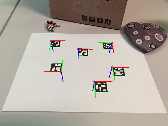
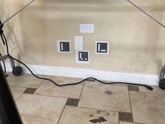
Here is what my fiducial placement looks like:
The left-most fiducial is at 0,0,1 in my coordinate system. I created a json that stores the positions and rotations of all of my fiducials. Here is what it looks like for this image:
{
    "0": { "translation" : [0,0,1], "rotation" : [0,0,0] },
    "1": { "translation" : [0,1,1], "rotation" : [0,0,0] },
    "2": { "translation" : [0,0.5,0.75], "rotation" : [0,0,0] }
}
The x,y,z values given here are the coordinates of the top-left corner of each fiducial. Also, you will need to account for rotation of the fiducials. These fiducials are on the north wall, which happens to be in the YZ plane. If they were on the southern wall, they would need to be rotated by 180 on the Z-axis.
This dictionary will be used to generate another dictionary that holds the coordinates of the corners of our fiducials. This representation will not be used directly by the program, but it is easier to read and edit. I also use feet as the measurement in this dictionary because I use American “freedom units” since that what comes on my tape measurer. It’s easy enough to convert to mm.
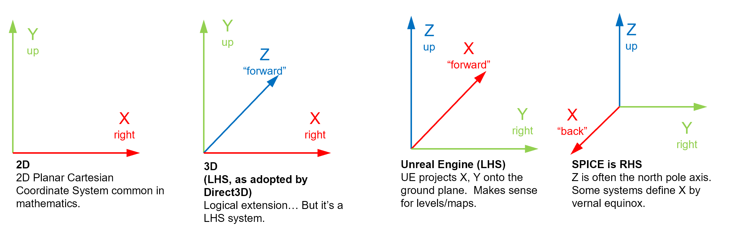
Helpful Tip: Pick a coordinate system that matches the coordinate system of your robotics program. ROS uses a right-handed coordinate system with Z-up. This often trips me up because I am used to Unity where Y is up and the coordinate system is left-handed. Picking the wrong coordinate system at the outset can really throw things off. In the above image, Z is up, X is coming out of the wall, and Y is along the wall. It looks like the right-most coordinate system in the image below.
Lastly, we want to store some representation of our Aruco fiducial corners. This can be done on the fly if you write a function that generates corners from the representation I showed earlier, or you can save it off to JSON. Here is my Python script saving off corners.
This should output the corner coordinates in a format like this:
{
    "0": [
        // Top-Left
        [
            0.0,
            0.0,
            304.79998779296875
        ],
        // Top-Right
        [
            0.0,
            80.0,
            304.79998779296875
        ],
        // Bottom-Right
        [
            0.0,
            80.0,
            224.79998779296875
        ],
        // Bottom-Left
        [
            0.0,
            0.0,
            224.79998779296875
        ]
    ]
}
Helpful Tip: The corners of the fiducials are detected with a certain “winding order” so it’s important that when you convert your position and orientation of fiducials into corner coordinates, you preserve this winding order. The order is: top left, top right, bottom right, bottom left.
Detecting the Fiducials
Next we will feed an image of fiducials into OpenCV and OpenCV will tell us which fiducial id’s it detected, as well as a bounding box corresponding to their corners.
import cv2
import cv2.aruco as aruco

# The image input needs to be grayscale
def findArucoMarkers(self, img, markerSize = 5, totalMarkers=250, draw=True):
        key = cv2.aruco.DICT_ARUCO_ORIGINAL # We are using the Original Dictionary
        arucoDict = aruco.Dictionary_get(key)
        arucoParam = aruco.DetectorParameters_create()
        bboxs, ids, rejected = aruco.detectMarkers(img, arucoDict, parameters = arucoParam)
        if draw:
            aruco.drawDetectedMarkers(img, bboxs)
        return [bboxs, ids]
This function will return the bounding boxes and ID’s of fiducials detected in the images. If draw is set to true, you will see the bounding boxes that are detected. Try taking a picture and running this code on it.
Helpful Tip: look at the 2D coordinates of the bounding box corners. Do they make sense? Do they match the winding order mentioned earlier? Try to think about how the image is being projected onto the image plane.
In the next step we will use these bounding boxes to perform pose estimation. Here is a link to the OpenCV docs if you want to read more: link to docs
Estimating Pose
Because the 3D points of the corners are known, and the camera matrix is known, we can solve for the extrinsic camera parameters (the translation and rotation). For the sake of brevity, I wont show how to load the camera parameters from json. Just know that they need to be converted into a numpy array to be fed into OpenCV. We will be using OpenCV’s built-in solvePNP method. The OpenCV documentation page is great at explaining the problem and the different solvers provided: docs.
We will be using SOLVEPNP_IPPE since we have more than 4 coplanar points. The full code is available here, I will just include a piece below that has the relevant parts.
    import cv2
    import numpy as np
    from numpy.linalg import inv

    solver_method = cv2.SOLVEPNP_IPPE

    def getPoseEstimatesFromImage(self, img, solver_method):

        # return the bounding boxes and id's
        points, ids = findArucoMarkers(img, markerSize = 5)
        print("Found %s markers"%len(ids))

        # Create empty arrays for our 2D and 3D points
        pose_estimate = None
        points_3D = np.empty((0,3), dtype=np.float32)
        points_2D = np.empty((0,2), dtype=np.float32)

        # We want to have arrays that match our 2D pixel coordinates to our known 3D corners
        for i in range(0, len(points)):
            if ids[i][0] in self.marker_dict:
                points_3D = np.concatenate((points_3D, self.marker_dict[ids[i][0]]))
                points_2D = np.concatenate((points_2D, points[i][0]))

        # Feed our 2D and 3D corresponding points into solvePnP
        success, rotation_vector, translation_vector = cv2.solvePnP(points_3D, points_2D, self.camera_matrix, self.dist_coeffs, flags=solver_method)

        if success:

            # convert to homogeneous transform matrix
            rmat, _ = cv2.Rodrigues(rotation_vector) # rotation vector to rotation matrix
            transform = np.eye(4, dtype=np.float32)
            transform[:3, :3] = rmat
            transform[:3, 3] = translation_vector.reshape(3)

            # compute the inverse to get absolute world position
            transform = inv(transform)

            pose_estimate = transform

        return success, pose_estimate
You might have noticed the line where we perform:
transform = inv(transform)
SolvePnP does not compute the position of our camera. It computes the extrinsic parameters of our camera. Our camera extrinsic matrix converts a point from world coordinates into camera coordinates.
We can write this as:
\(T_{w}P_{w}=P_{c}\)
Since we want the camera position in world coordinates, we want an equation that transforms from camera coordinates to world coordinates. If we multiply both sides by the inverse of the camera extrinisic matrix we get:
\(T^{-1}_{w}T_{w}P_{w}=T^{-1}_{w}P_{c}\)
\(P_{w}=T^{-1}_{w}P_{c}\)
So the inverse transform of our camera extrinsic matrix maps a point from camera space to world space. Since our camera is its own origin, we can represent its transform by the identity matrix.
\(P_{c} = I\) so we can substitute it in:
\(P_{w}=T^{-1}_{w}I\)
\(P_{w}=T^{-1}_{w}\)
So the homogeneous transform matrix representing our camera’s transform in world space is just the inverse of the camera extrinsic matrix. The way I think of inverse matrices is that they “undo” what the original matrix did. It makes sense intuitively in this case I think.
Congratulations!
Now you have the basic knowledge needed to do pose estimation with fiducials! This is a pretty powerful method since you can use it to track objects or localize your robot with just one camera. If you get stuck or have any questions feel free to email me at sebaslogo@gmail.com and I will try to get back to you quickly!